My final project
For My final project I decided to build a smart robot that can detect small object and pick them. As well as being used to remove trash from the streets this robot can also be used at home to help cleaning and tidying rooms.
HOW DOES IT WORK?
Materials
MOTORS:
- x2) stepper motor Nema 17HS13-0404S1 Link (similiar motor)
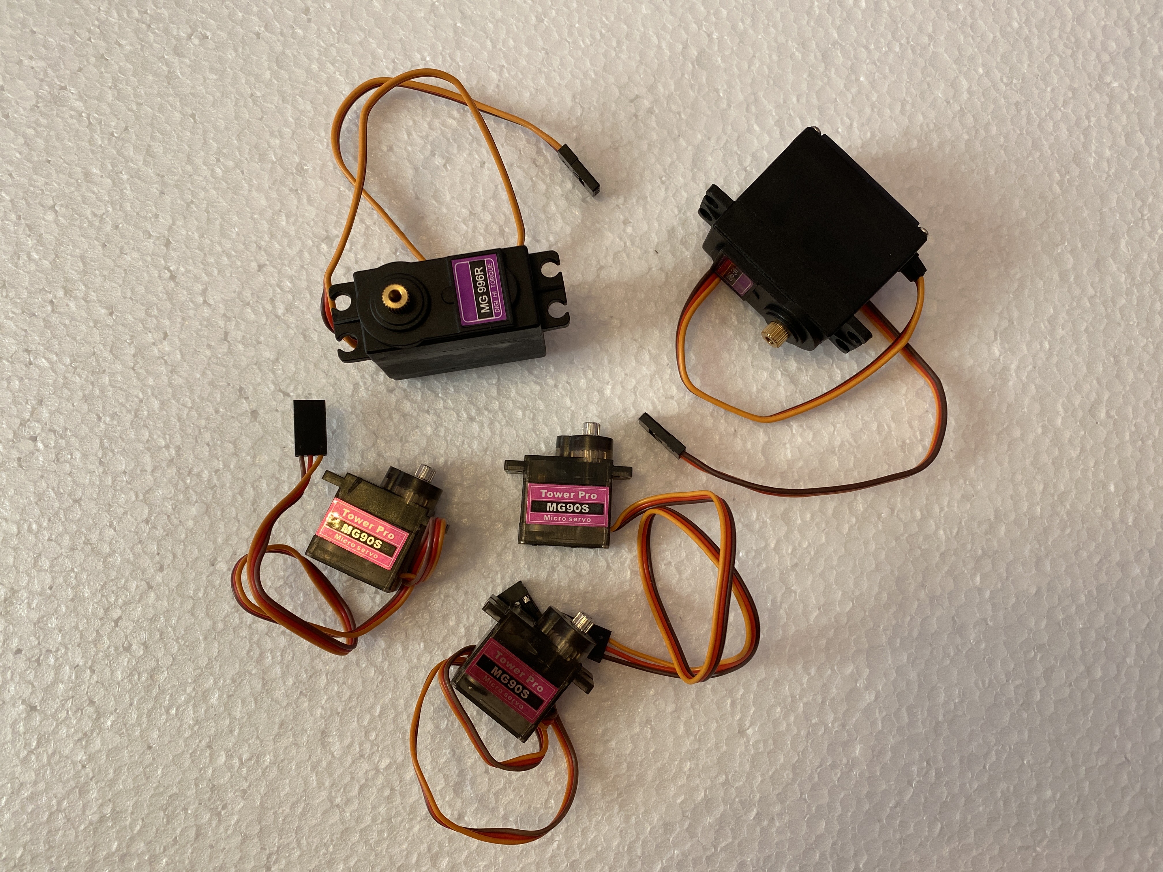
- x4) 6Pcs MG90S Metal Geared Micro Servo Motor Amazon Link
- x2) 2Pcs MG996R Metal Geared Servo Motor Amazon Link
BOARDS AND MOTOR DRIVERS:
- x1) Huzzah ESP32 Feather Amazon Link
- x1) protoboard Amazon Link
- x2) stepper motor Driver A4988 Amazon Link
- x1) Cnc Shield Amazon Link
- x1) Servo driver PCA9685 Amazon Link
SENSORS:
- x3) GY-VL53L0XV2 L53L0X TOF Sensor Amazon Link
WHEELS:
- x2) Wheels Amazon Link
- x1) Swivel wheel Amazon Link
CONNECTIONS:
- x1) Dupont cable kit Amazon Link
- x1) Jumper dupont cable Amazon Link
- x1) USB connector Amazon Link
- x2) USB cables Amazon Link
- x1) Battery holder Amazon Link
- x1) Terminal block connector Amazon Link
- x1) pin strip kit Amazon Link
POWER:
- x3) Lithium battery 3.7 V Amazon Link
OTHER:
- x1) LM2596S DC-DC 24 V / 12 V to 5V 5A converter Amazon Link
- x1) switch Amazon Link
- x2) resistor 1k Amazon Link
- x1) Hexagonal spacers kit Amazon Link
- x1) Screw kit Amazon Link
- x1) Insulant tape Amazon Link
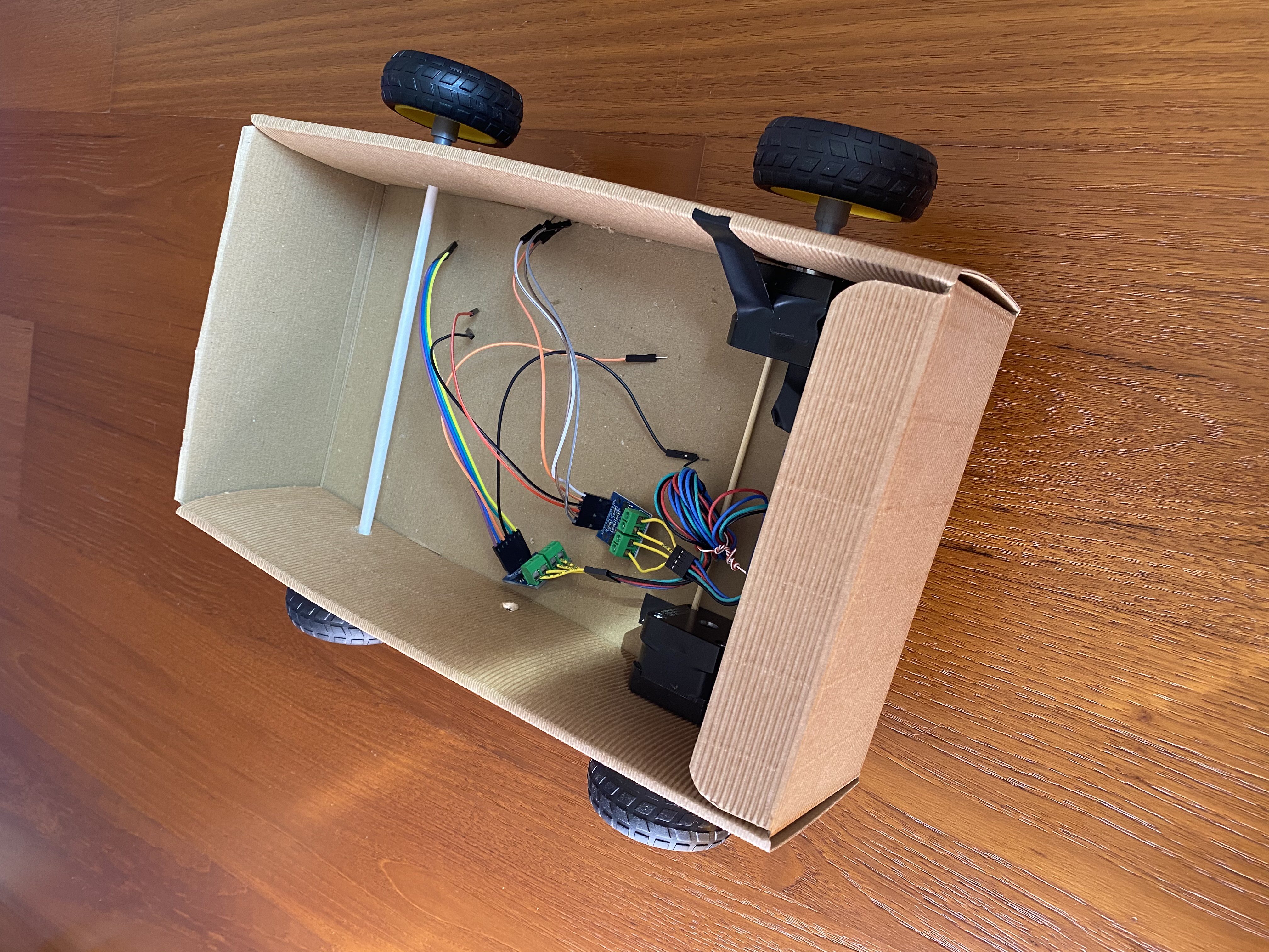
Firstly I created a Cad of my project with fusion 360. In this CAD I included two traction wheels, two wheels not attached to motors and a swivel wheel because I didn't know if my project would have worked best with four wheels (that give more stability) or with two wheels and a swivel wheel (that allows to turn more easily).
Then I made two prototypes:
First prototype:
Second prototype:
The second prototype turned better and was stable enough so I decided to use the swivel wheel for my final project.
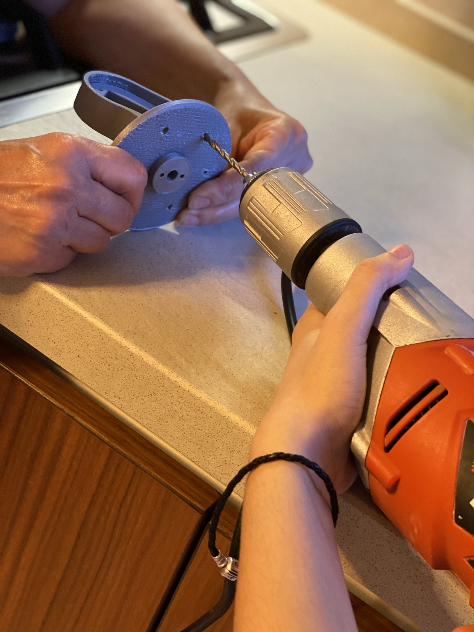
3D PRINTING AND LASER CUTTING:
I laser cut the two bases of my machine:
This are the components I designed on Fusion and 3D printed:
- Download my STL file
- Download my STL file
- Download my STL file
To laser cut and 3D print my components I have been helped by Centro Piaggio labs.
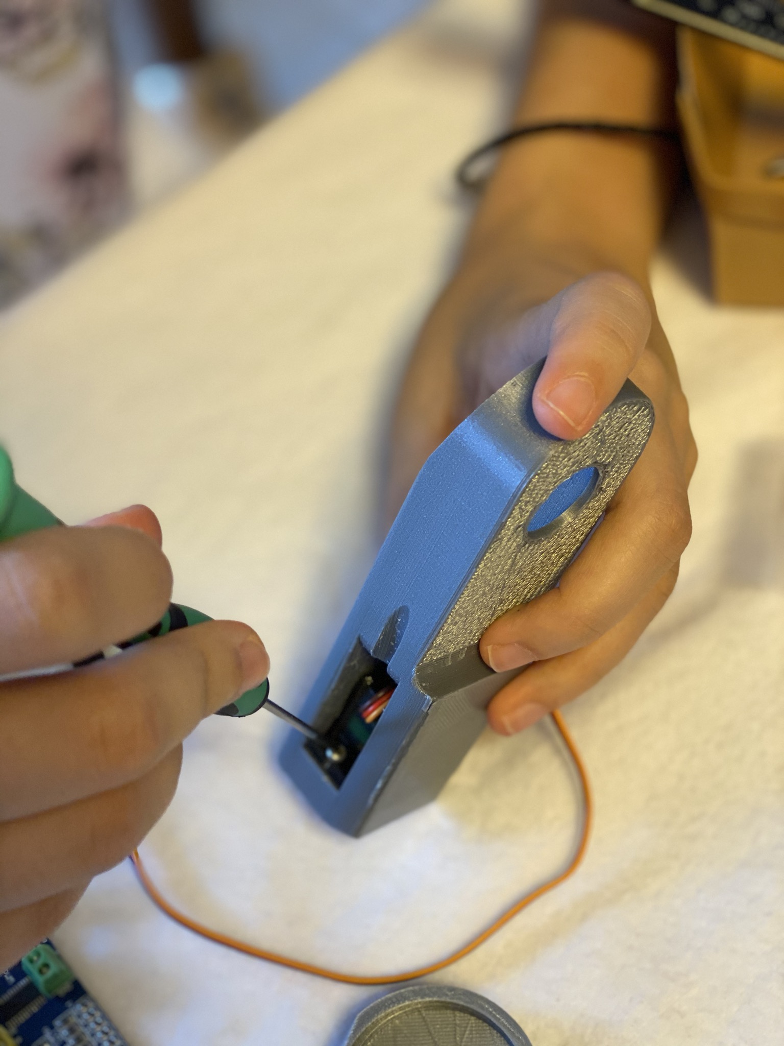
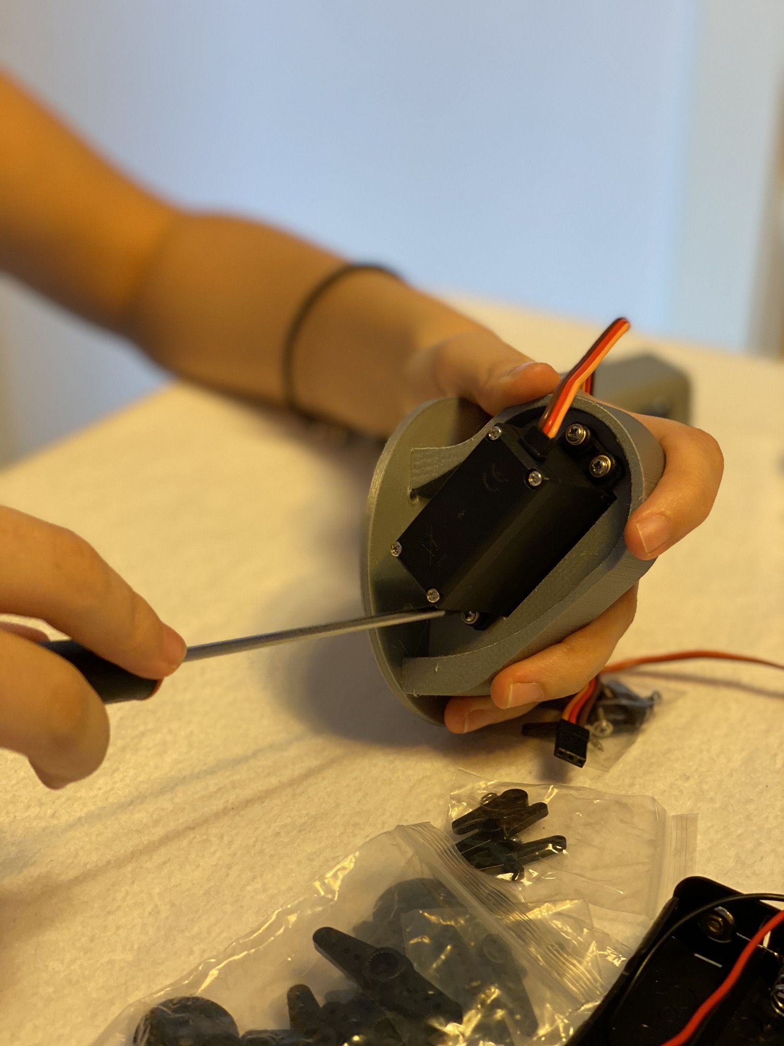
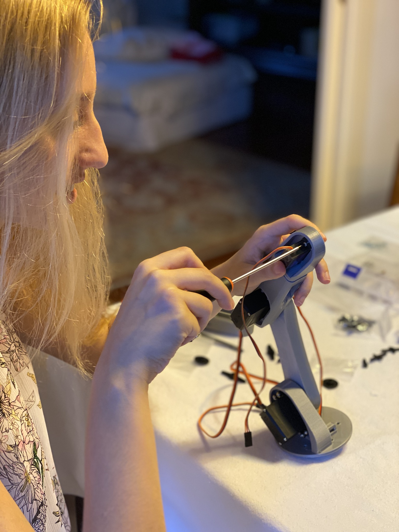
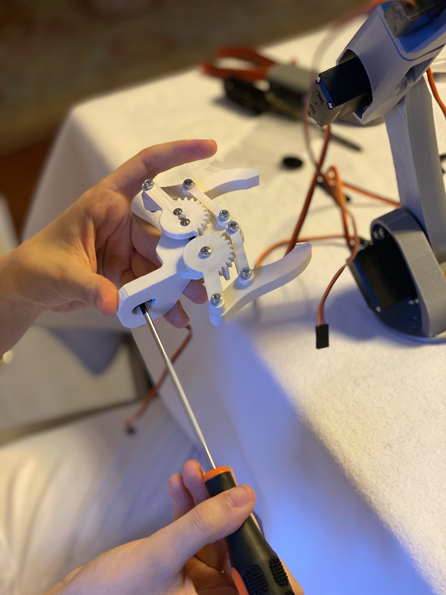
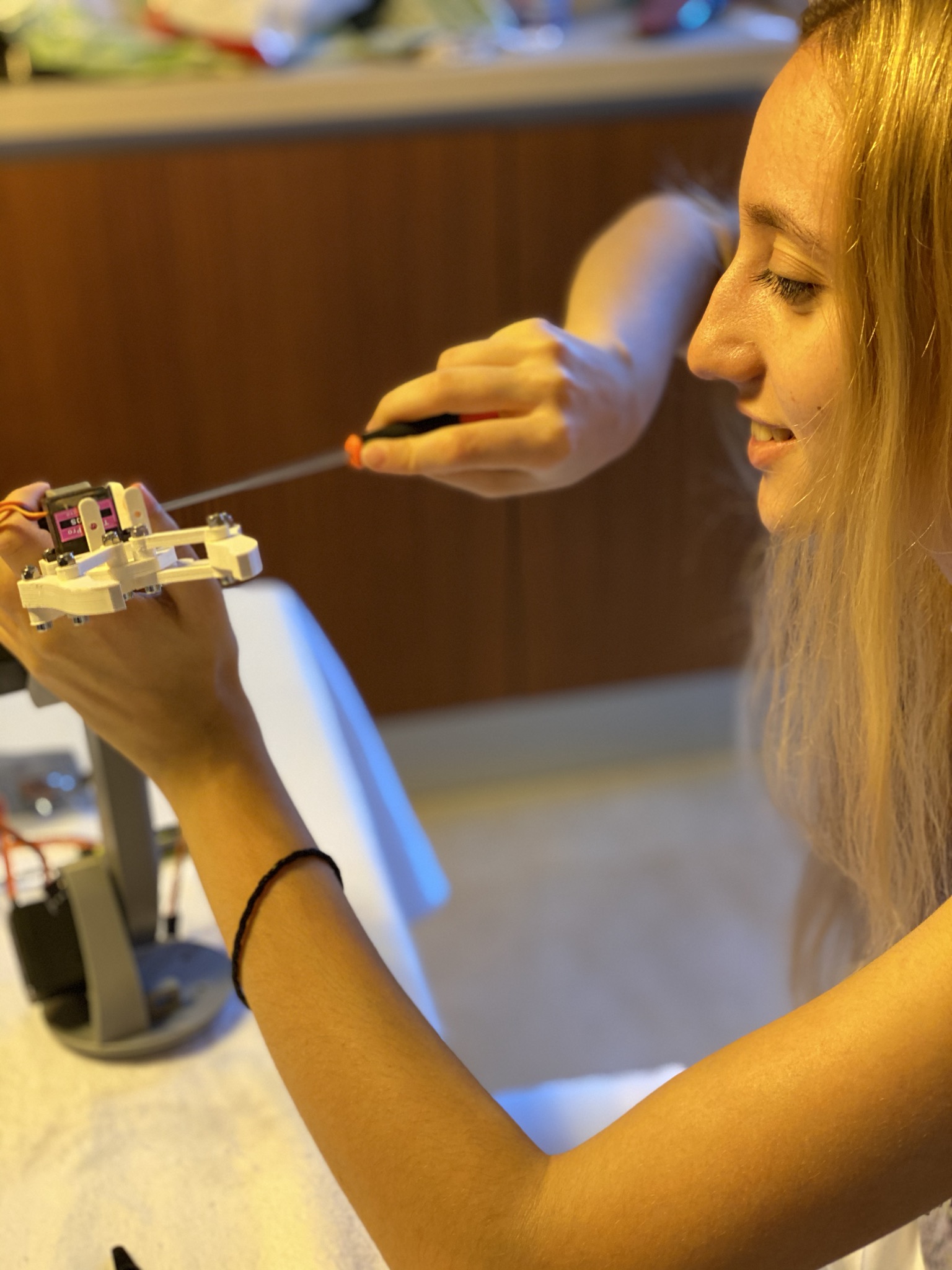
MECHANICAL ARM:
I found the mechanical arm I wanted to include in my project online but I had to modify some parts to fit my project. Here is a link to the page where I found the mechanical arm I used.
3D printed parts:
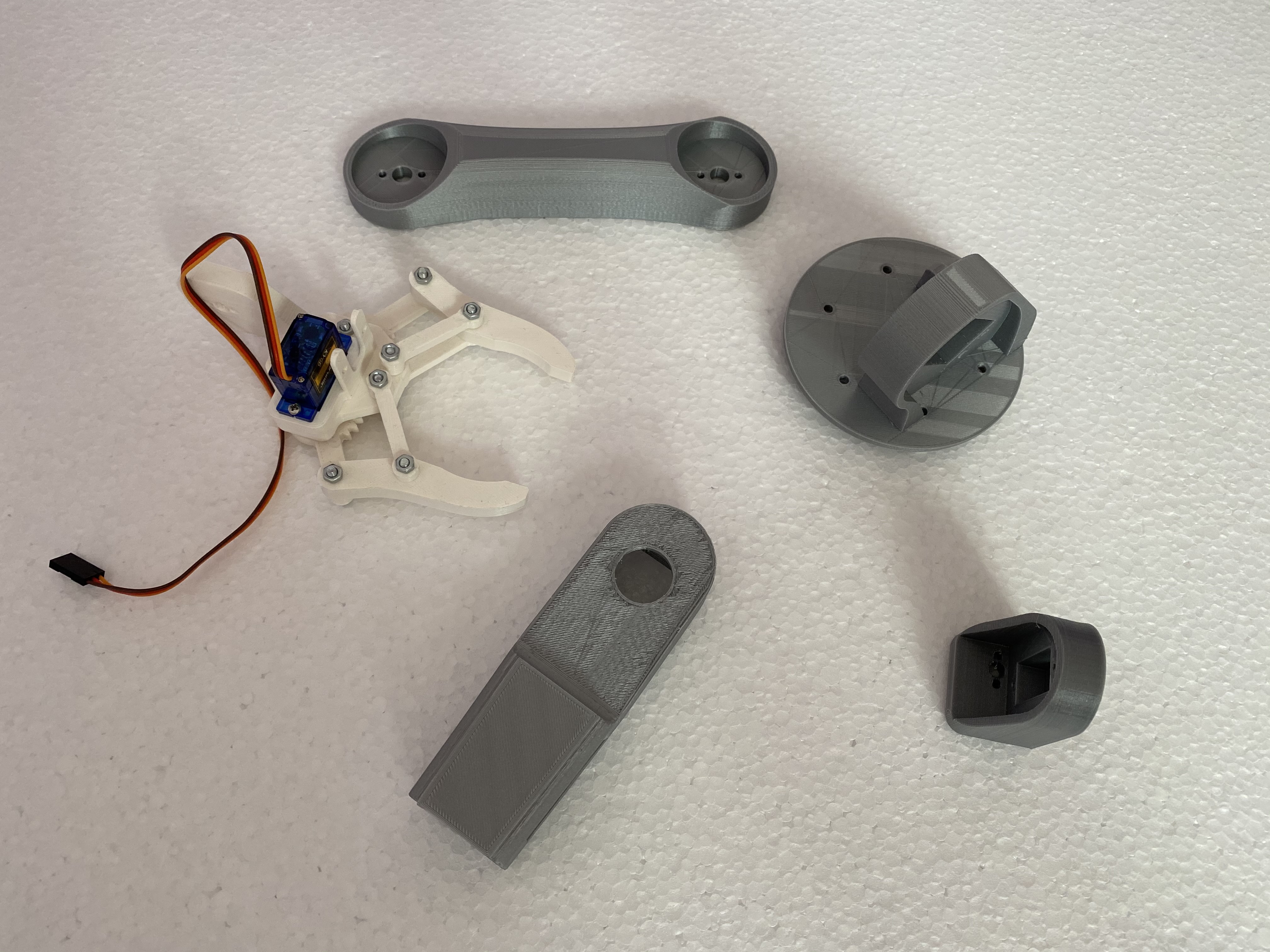
Motors:
Assembling:
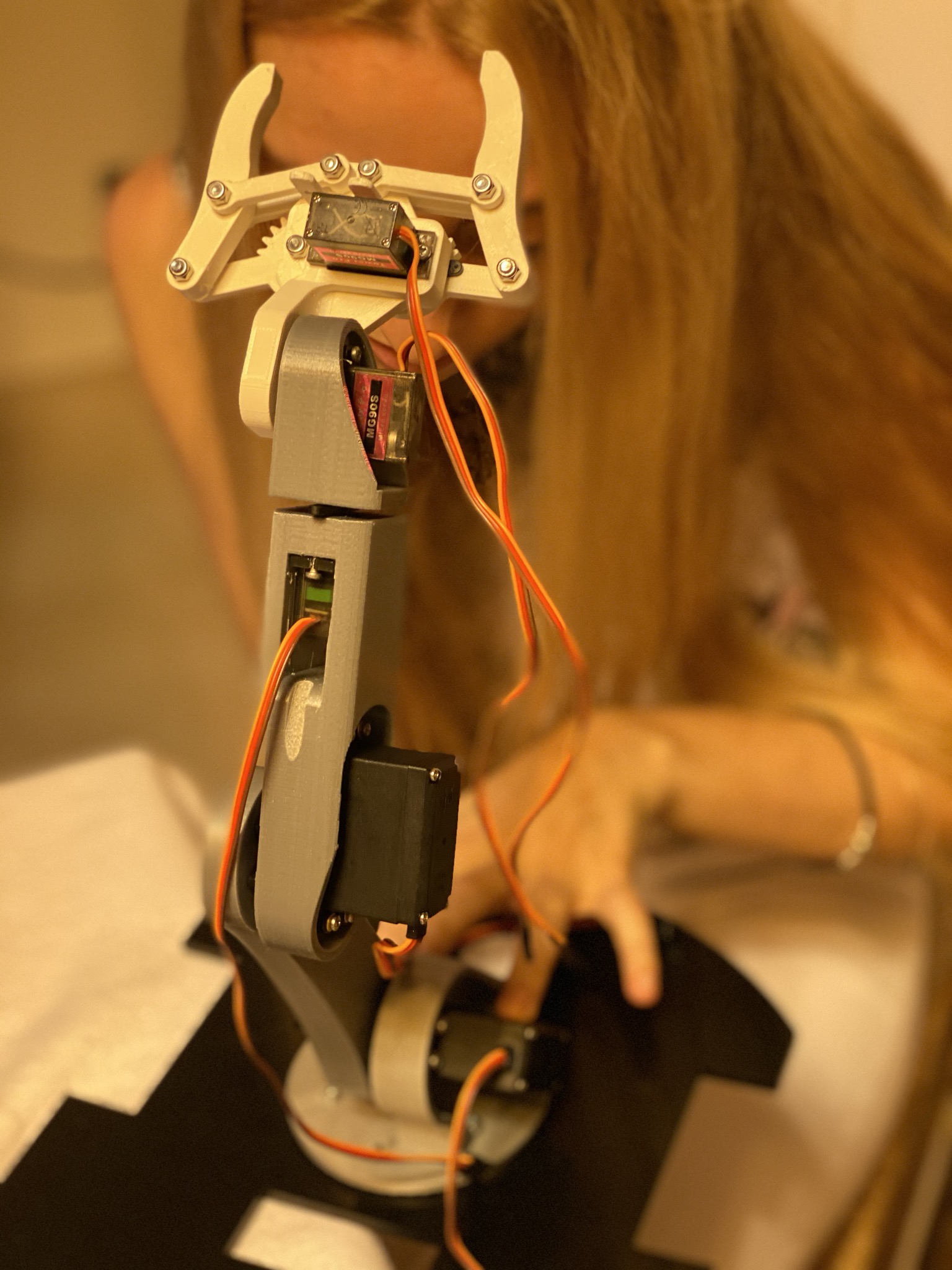
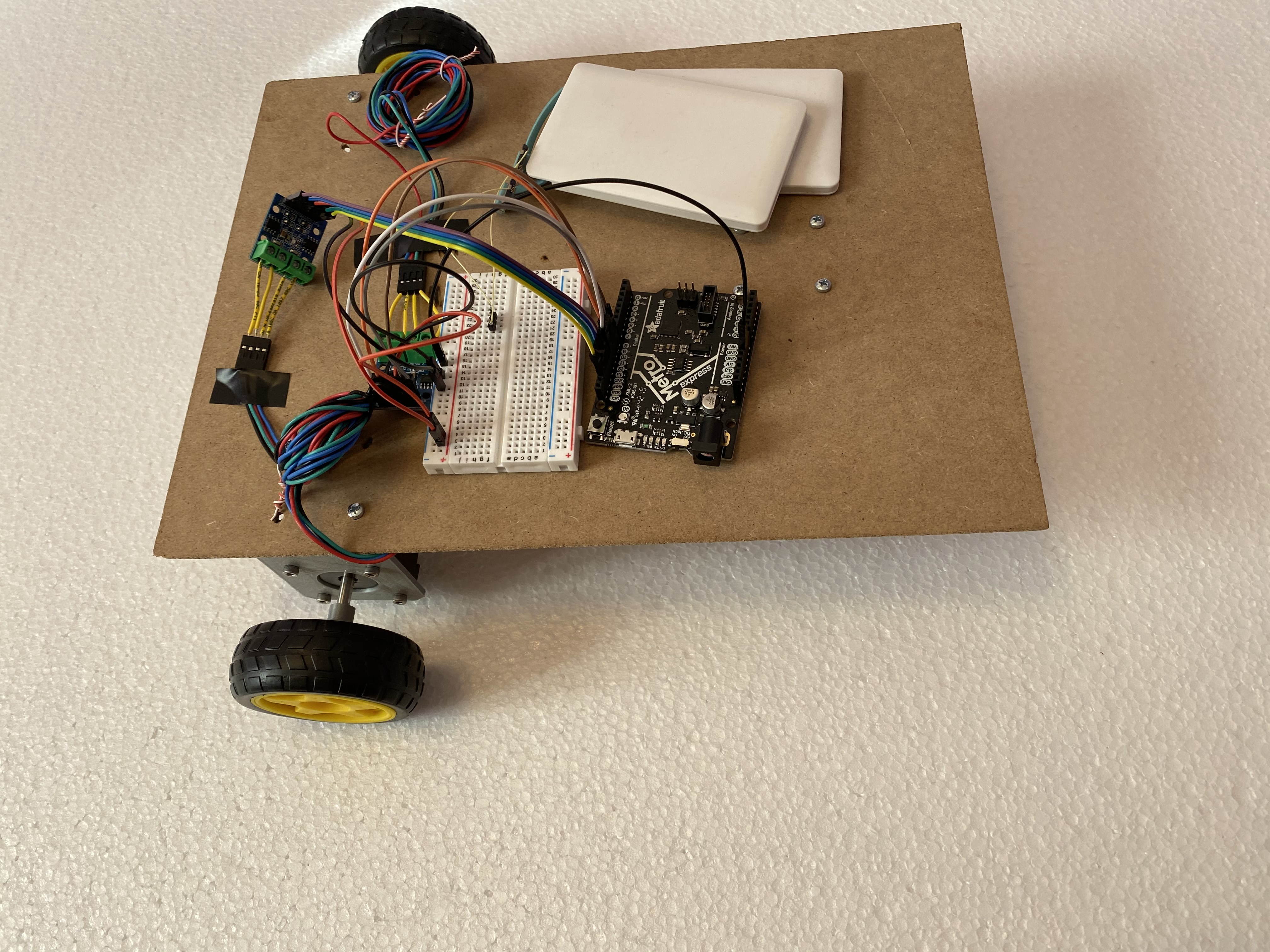
ELECTRONICS
At first I used the Metro board for this project because I needed many pins and this board has more pins that can be used for basically any purpose, but then I realised that The Huzzah board might be more useful since it can be connected to wifi.
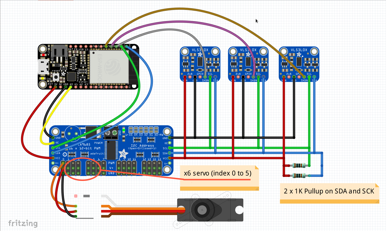
I needed to use 3 sensors and drive 2 stepper motors and 4 servo motors at the same time: this could require 14 output pins (and the Huzzah only has 10) if I connected everything directly to the board so I had to find a solution to use less pin as possible.
This is the solutions I found:
- Use a PCA9685 Servo driver
- use a protoboard
This driver allows you to run up to 16 servo motors using only 1 output pin, 1 SCL and 1 SDA pin.
I soldered some GROUND, +3V, SCL and SDA connection on a protoboard so that I could connect my sensor to those and instead of using more pins.
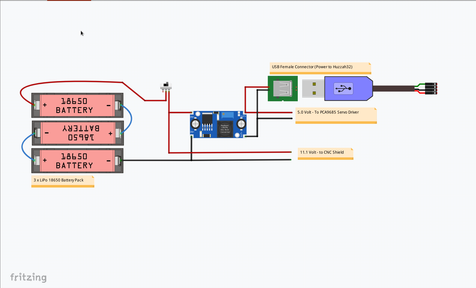
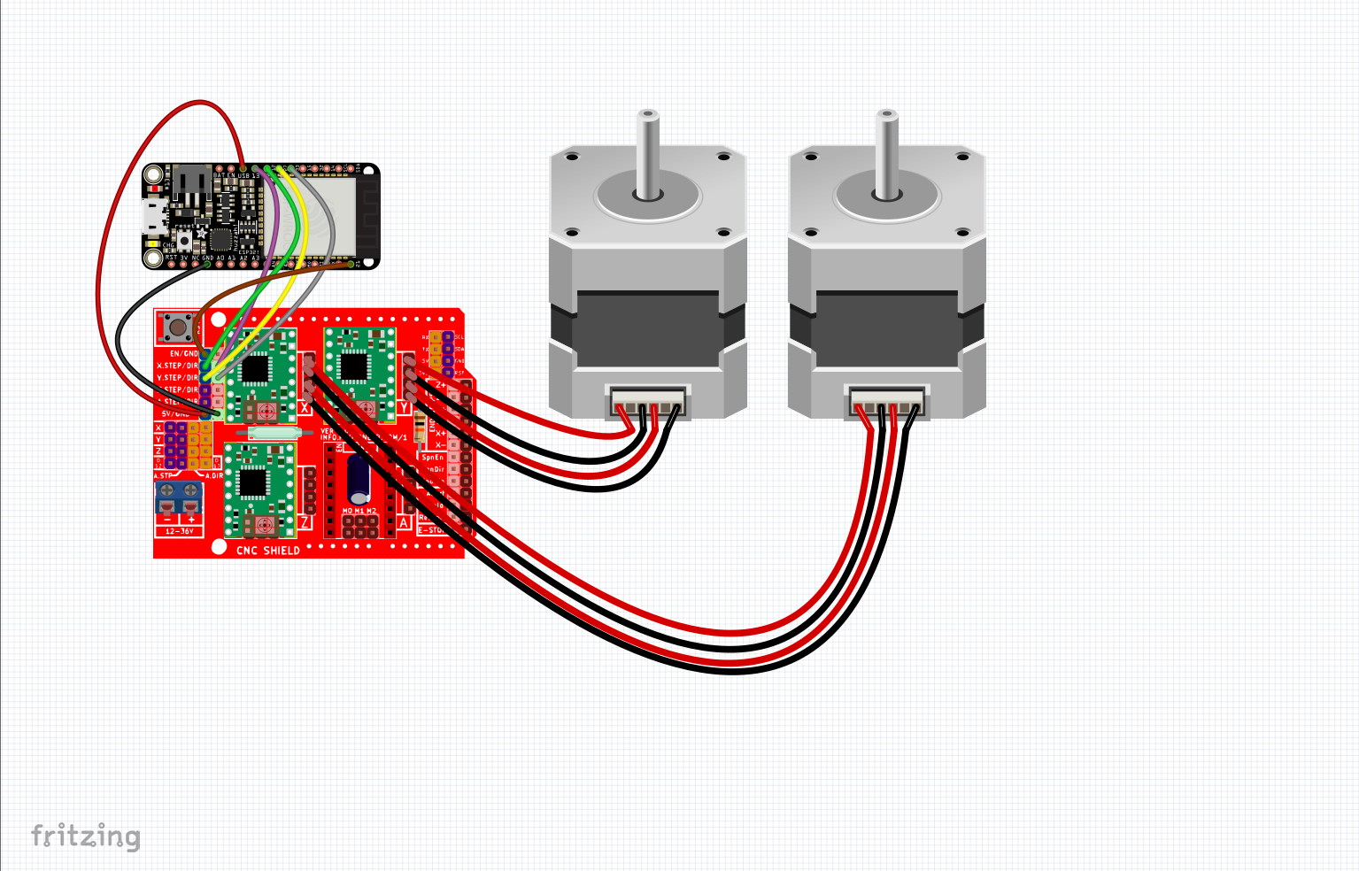
This are my circuit diagrams:
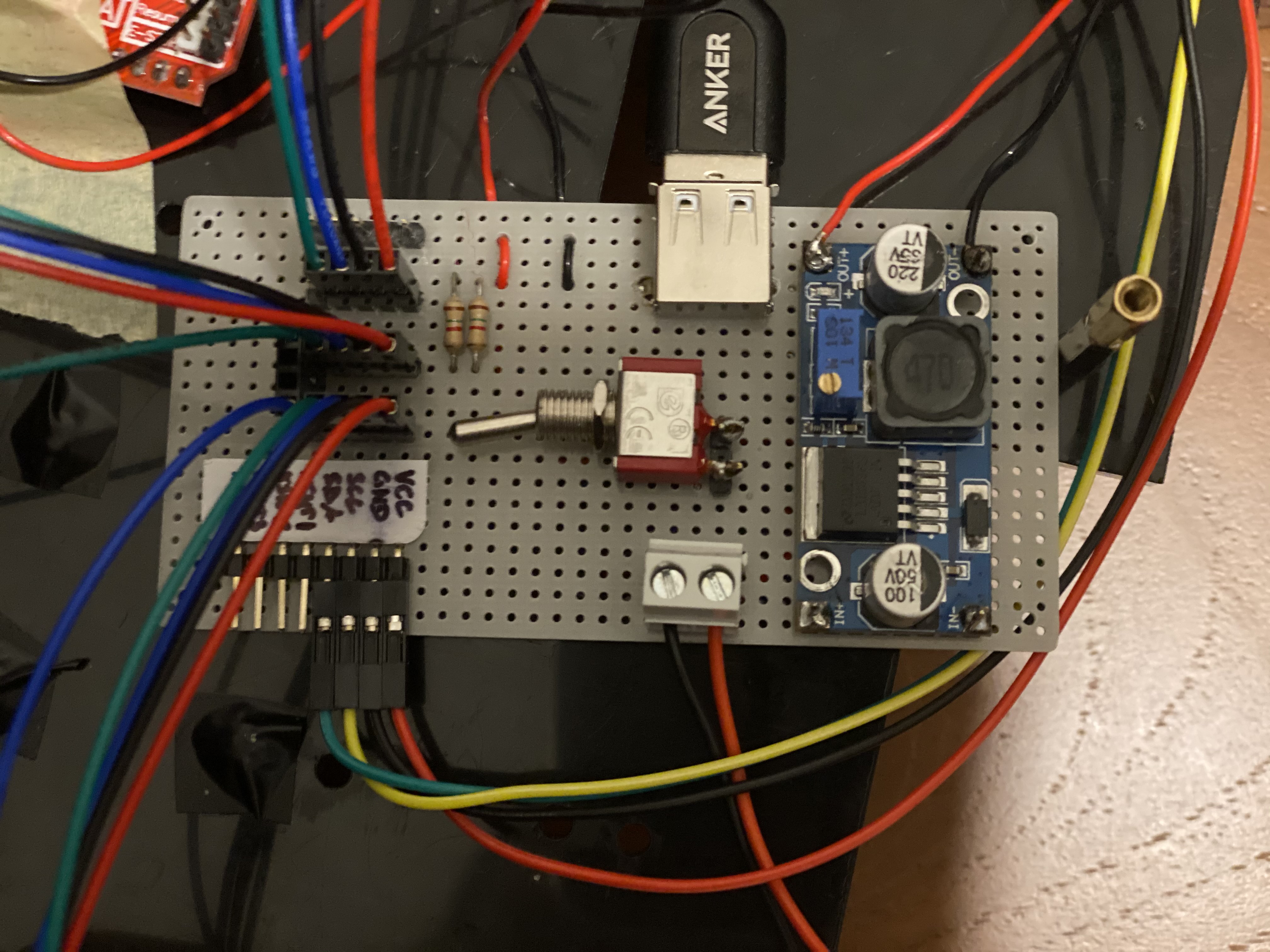
This is the protoboard I soldered:
Our stepper motors need 12 volts to make a strong torque, since my machine was heavy I nedded the max possible power for my motors so I used three lithium batteries of 3.5 V each.
To drive the stepper motors with the A4988 driver I have found these two websites very helpful:
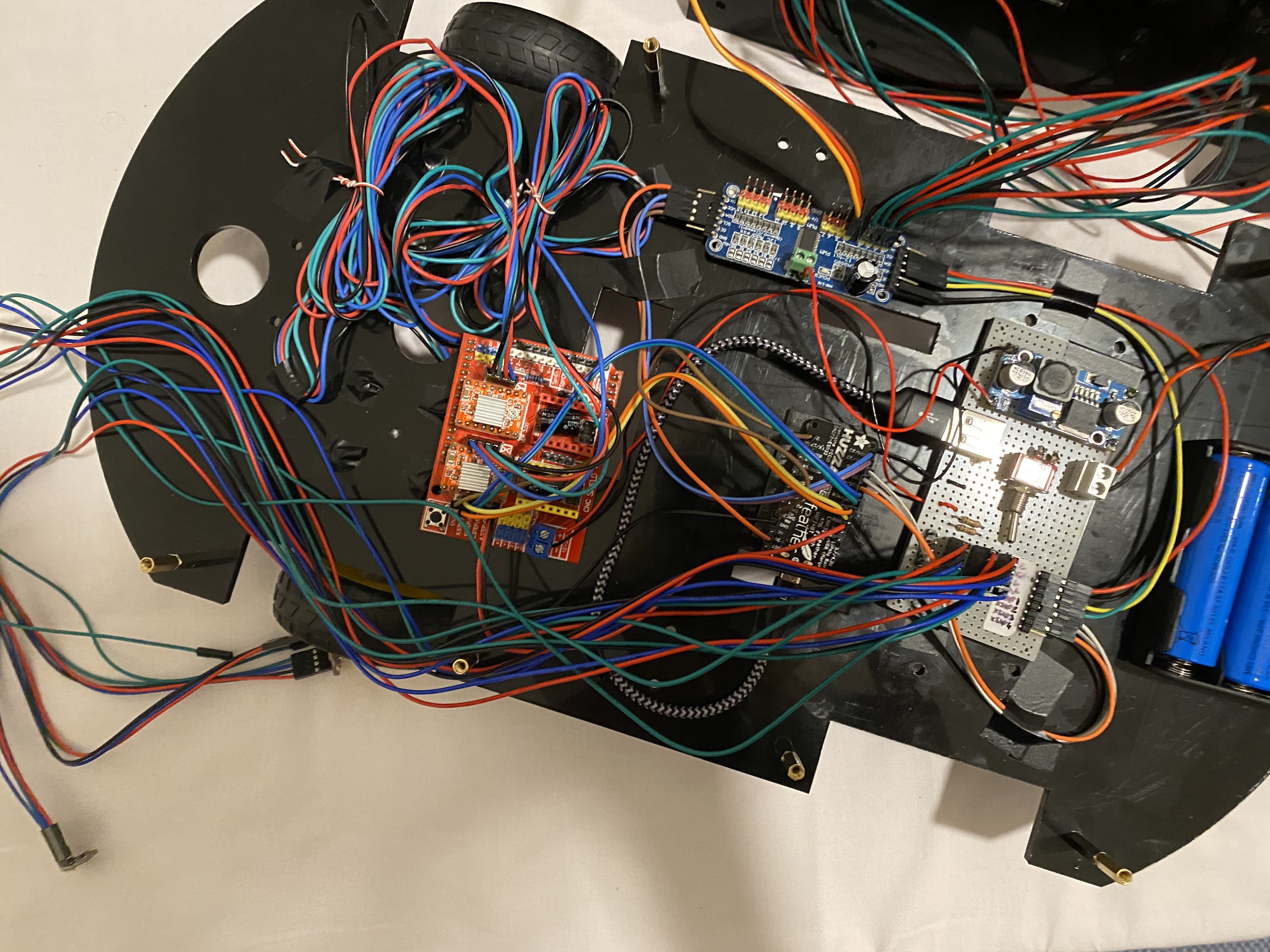
This is my final circuit, the wires were too many so it was easy to get confused, plug a wire in the wrong place and burn a motor so I used some insulant tape to make the circuit easier to understand. After I made a short and burnt a motor driver because a ground and a 12 V connection where both touching a screw I also covered the screws with insulant tape.
ARDUINO CODING
To write my arduino code I divided my project into its main 3 parts: stepper motors circuit, mechanical arm and sensor. I started by looking at the examples and modified them to fit my project. I used "dual sensor" from the library Adafruit_VL53LOX and I added one sensor. I also used the example "servo" from the library Adafruit_PWMServoDriver. After I tried all those separately I started writing my own code using parts of the examples and defining my own functions.
This is the final version of my arduino code:
#include < Adafruit_VL53L0X.h>
#include < Adafruit_PWMServoDriver.h>
/* Stepper motor defines */

#define STEPS_PER_REVOLUTION 200  // NEMA 17 has 200 Steps per revolution
#define  MM_WHEEL_LENGTH  200     // Space per revolution
#define STEPS_TO_TURN  170        // Motor steps to turn 90 degree

#define STP_EN    21              // Enable motor current

//Direction pin - Left and Right wheel
#define X_DIR     13
#define Y_DIR     33

//Step pins - Left and Right wheel
#define X_STP     12
#define Y_STP     27

/* Laser sensors defines */
#define SHT_LOX1 14
#define SHT_LOX2 32
#define SHT_LOX3 15

// Addresses for the three VL53L0X sensors
#define LOX1_ADDRESS 0x30
#define LOX2_ADDRESS 0x31
#define LOX3_ADDRESS 0x32

// Calibration Values for the three VL53L0X sensors (before starting make sure you claibrate your sensors)
#define LOX1_CALIB   -7
#define LOX2_CALIB   -30
#define LOX3_CALIB   -10

#define VL53_OUT_OF_RANGE 1500


//defines for servo motors
// Depending on your servo make, the pulse width min and max may vary, you
// want these to be as small/large as possible without hitting the hard stop
// for max range. You'll have to tweak them as necessary to match the servos you
// have!
#define NUMSERVOS 16   // Total number of servo in the system
#define SERVOMIN  410 // This is the 'minimum' pulse length count (out of 4096)
#define SERVOMAX  820 // This is the 'maximum' pulse length count (out of 4096)
#define USMIN  600.0 // This is the rounded 'minimum' microsecond length of the PWM Pulse
#define USMAX  2400.0 // This is the rounded 'maximum' microsecond length of the PWM Pulse
#define SERVO_FREQ 45 // Analog servos run at ~100 Hz updates
#define SERVO_USEC_PERIOD (1000000 / SERVO_FREQ)// Servo period in microseconds
#define SERVO_OEPIN 26

int ServoDelay[6] = { 20, 20, 5, 5, 5, 10} ; // Each Servo moves better at his own speed

// objects for the vl53l0x
Adafruit_VL53L0X lox1 = Adafruit_VL53L0X();
Adafruit_VL53L0X lox2 = Adafruit_VL53L0X();
Adafruit_VL53L0X lox3 = Adafruit_VL53L0X();

//use this variables to store sensors values (calibrated)
int VL53_Calib_Readout_1;
int VL53_Calib_Readout_2;
int VL53_Calib_Readout_3;

// objects for PCA9685 Servo driver
// called this way, it uses the default address 0x40
Adafruit_PWMServoDriver pwm = Adafruit_PWMServoDriver();

/* Stepper motor related variables */
int mot_steps ;
int last_turn_dir = 0; // variable for scanning right=0 left=1
int wall_warning = 0; // multi level wall warning . to avoid false alarms

// Laser Sensors variables
// this holds the measurement (not calibrated I have found out that there is an offset in the measurements)
VL53L0X_RangingMeasurementData_t measure1;
VL53L0X_RangingMeasurementData_t measure2;
VL53L0X_RangingMeasurementData_t measure3;

// Servo variables
int Current_Servo_Position[NUMSERVOS];

/* Stepper motor related functions */

void move_forward(int speed, int mm_space) // convert distances into steps and move both wheel forward
{
  digitalWrite(STP_EN, LOW);
  digitalWrite(X_DIR, HIGH);
  digitalWrite(Y_DIR, HIGH);
  mot_steps = (STEPS_PER_REVOLUTION * mm_space) / MM_WHEEL_LENGTH;
  for (int i = 0; i <= mot_steps; i++) {
    digitalWrite(X_STP, HIGH);
    delayMicroseconds(speed);
    digitalWrite(Y_STP, HIGH);
    delayMicroseconds(speed);
    digitalWrite(X_STP, LOW);
    delayMicroseconds(speed);
    digitalWrite(Y_STP, LOW);
    delayMicroseconds(speed);
  }
  digitalWrite(STP_EN, HIGH);
}


void turn_right(int speed) //turn right by making the right wheel move forward and the left one move back
{
  digitalWrite(STP_EN, LOW);
  digitalWrite(X_DIR, HIGH);
  digitalWrite(Y_DIR, LOW);
  for (int i = 0; i <= STEPS_TO_TURN; i++) {
    digitalWrite(X_STP, HIGH);
    delayMicroseconds(speed);
    digitalWrite(Y_STP, HIGH);
    delayMicroseconds(speed);
    digitalWrite(X_STP, LOW);
    delayMicroseconds(speed);
    digitalWrite(Y_STP, LOW);
    delayMicroseconds(speed);
  }
  digitalWrite(STP_EN, HIGH);
}

void turn_left(int speed) //turn left by making the left wheel move forward and the right one move back
{
  digitalWrite(STP_EN, LOW);
  digitalWrite(X_DIR, LOW);
  digitalWrite(Y_DIR, HIGH);
  for (int i = 0; i <= STEPS_TO_TURN; i++) {
    digitalWrite(X_STP, HIGH);
    delayMicroseconds(speed);
    digitalWrite(Y_STP, HIGH);
    delayMicroseconds(speed);
    digitalWrite(X_STP, LOW);
    delayMicroseconds(speed);
    digitalWrite(Y_STP, LOW);
    delayMicroseconds(speed);
  }
  digitalWrite(STP_EN, HIGH);
}

// Set Addresses to communicate with laser Sensors
void setID() {
  // all reset
  digitalWrite(SHT_LOX1, LOW);
  digitalWrite(SHT_LOX2, LOW);
  digitalWrite(SHT_LOX3, LOW);
  delay(10);
  // all unreset
  digitalWrite(SHT_LOX1, HIGH);
  digitalWrite(SHT_LOX2, HIGH);
  digitalWrite(SHT_LOX3, HIGH);
  delay(10);

  // activating LOX1 and reseting LOX2
  digitalWrite(SHT_LOX1, HIGH);
  digitalWrite(SHT_LOX2, LOW);
  digitalWrite(SHT_LOX3, LOW);
  // initing LOX1
  if (!lox1.begin(LOX1_ADDRESS)) {
    Serial.println(F("Failed to boot first VL53L0X"));
  }
  delay(10);

  // activating LOX2
  digitalWrite(SHT_LOX2, HIGH);
  delay(10);

  //initing LOX2
  if (!lox2.begin(LOX2_ADDRESS)) {
    Serial.println(F("Failed to boot second VL53L0X"));
  }

  // activating LOX3
  digitalWrite(SHT_LOX3, HIGH);
  delay(10);

  //initing LOX3
  if (!lox3.begin(LOX3_ADDRESS)) {
    Serial.println(F("Failed to boot third VL53L0X"));
  }
}


void init_steppers() { // initialize motors

  // put stp and dir X and Y pins in output
  pinMode(X_DIR, OUTPUT); pinMode(X_STP, OUTPUT);
  pinMode(Y_DIR, OUTPUT); pinMode(Y_STP, OUTPUT);
  pinMode(STP_EN, OUTPUT);
  digitalWrite(STP_EN, HIGH);
}


void init_sensors() { //initializig sensors
  pinMode(SHT_LOX1, OUTPUT);
  pinMode(SHT_LOX2, OUTPUT);
  pinMode(SHT_LOX3, OUTPUT);

  Serial.println("Shutdown pins inited...");
  digitalWrite(SHT_LOX1, LOW);
  digitalWrite(SHT_LOX2, LOW);
  digitalWrite(SHT_LOX3, LOW);
  Serial.println("All sensors in reset mode...(pins are low)");

  Serial.println("Starting...");
  setID();
}


void init_ServoDriver() { //initialize servo driver
  // put your setup code here, to run once:
  pinMode(SERVO_OEPIN, OUTPUT);
  digitalWrite(SERVO_OEPIN, LOW);
  pwm.begin();
  /*
     In theory the internal oscillator (clock) is 25MHz but it really isn't
     that precise. You can 'calibrate' this by tweaking this number until
     you get the PWM update frequency you're expecting!
     The int.osc. for the PCA9685 chip is a range between about 23-27MHz and
     is used for calculating things like writeMicroseconds()
     Analog servos run at ~50 Hz updates, It is important to use an
     oscilloscope in setting the int.osc frequency for the I2C PCA9685 chip.
     1) Attach the oscilloscope to one of the PWM signal pins and ground on
        the I2C PCA9685 chip you are setting the value for.
     2) Adjust setOscillatorFrequency() until the PWM update frequency is the
        expected value (50Hz for most ESCs)
     Setting the value here is specific to each individual I2C PCA9685 chip and
     affects the calculations for the PWM update frequency.
     Failure to correctly set the int.osc value will cause unexpected PWM results
  */
  pwm.setOscillatorFrequency(25500000);
  pwm.setPWMFreq(SERVO_FREQ);  // Analog servos run at ~100 Hz updates
  delay(10);

}

int AngletoPWM(int angle) // this function converts an angle into the rigth values for the pwm
{
  float usecs = ((float)(angle) / 180.0) * (USMAX - USMIN) + USMIN;
  return ((int)((usecs * 4096.0) / SERVO_USEC_PERIOD));

}

void SetServoPos(int servoindex, int angle) //changes the angle of a servo and update the variable that stores that datum
{
  pwm.setPWM(servoindex, 0, AngletoPWM(angle));
  Current_Servo_Position[servoindex] = angle;
}

void GotoServoPos(int servoindex, int angle) //gradually go to to an angle
{
  int StartPWM = AngletoPWM(Current_Servo_Position[servoindex]);
  int EndPWM = AngletoPWM(angle);
  if (EndPWM > StartPWM) {
    for (int j = StartPWM; j <= EndPWM; j++) { //go to an angle if the current angle is smaller than the required one
      pwm.setPWM(servoindex, 0, j);
      delay(ServoDelay[servoindex]); // Each servo has its own speed
    }
  }
  else if (EndPWM < StartPWM)
    for (int j = StartPWM; j >= EndPWM; j--) { //go to an angle if the current angle is bigger than the required one
      pwm.setPWM(servoindex, 0, j);
      delay(ServoDelay[servoindex]); // Each servo has its own speed
    }
  Current_Servo_Position[servoindex] = angle;
}


void Servo_Idle() { // position of the mechanical arm when is not picking

  SetServoPos(0, 90);
  SetServoPos(1, 90);
  SetServoPos(2, 90);
  SetServoPos(3, 90);
  SetServoPos(4, 75);
}


void ServoPick() { // sequence to pick an object
  GotoServoPos(0, 30);
  GotoServoPos(3, 10);
  GotoServoPos(1, 160);
  GotoServoPos(4, 25);
  delay(1000);
  GotoServoPos(0, 105);
  GotoServoPos(1, 15);
  GotoServoPos(3, 150);
  GotoServoPos(4, 80);


}


void Read_Laser_sensors() {

  lox1.rangingTest(&measure1, false); // pass in 'true' to get debug data printout!
  lox2.rangingTest(&measure2, false); // pass in 'true' to get debug data printout!
  lox3.rangingTest(&measure3, false); // pass in 'true' to get debug data printout!

  // print sensor one reading
  Serial.print("1: ");
  if (measure1.RangeStatus != 4) {    // if not out of range
    VL53_Calib_Readout_1 = measure1.RangeMilliMeter + LOX1_CALIB;
    Serial.print(VL53_Calib_Readout_1);
  } else {
    VL53_Calib_Readout_1 = VL53_OUT_OF_RANGE;
    Serial.print("Out of range");
  }
  if (VL53_Calib_Readout_1 > VL53_OUT_OF_RANGE) { // for some strange reason it may happen that instead of out of range whe have a very big reading
    VL53_Calib_Readout_1 = VL53_OUT_OF_RANGE;
  }

  Serial.print(" ");

  Serial.print("2: ");
  if (measure2.RangeStatus != 4) {    // if not out of range
    VL53_Calib_Readout_2 = measure2.RangeMilliMeter + LOX2_CALIB;
    Serial.print(VL53_Calib_Readout_2);
  } else {
    VL53_Calib_Readout_2 = VL53_OUT_OF_RANGE;
    Serial.print("Out of range");
  }
  if (VL53_Calib_Readout_2 > VL53_OUT_OF_RANGE) { // for some strange reason it may happen that instead of out of range whe have a very big reading
    VL53_Calib_Readout_2 = VL53_OUT_OF_RANGE;
  }

  Serial.print(" ");

  // print sensor three reading
  Serial.print("3: ");
  if (measure3.RangeStatus != 4) {    // if not out of range
    VL53_Calib_Readout_3 = measure3.RangeMilliMeter + LOX3_CALIB;
    Serial.print(VL53_Calib_Readout_3);
  } else {
    VL53_Calib_Readout_3 = VL53_OUT_OF_RANGE;
    Serial.print("Out of range");
  }
  if (VL53_Calib_Readout_3 > VL53_OUT_OF_RANGE) { // for some strange reason it may happen that instead of out of range whe have a very big reading
    VL53_Calib_Readout_3 = VL53_OUT_OF_RANGE;
  }
}


void Scan_and_move() { //read the values of the sensor and decide if there is an object an obstacle or nothing in your path
  int DiffData = 0;
  Read_Laser_sensors();
  if ((VL53_Calib_Readout_1 > 600) and (VL53_Calib_Readout_2 > 600)) // there is nothing near the machine can move forward
  {
    move_forward(2000, 500);

  }


  else {
    DiffData = abs(VL53_Calib_Readout_1 - VL53_Calib_Readout_2);

    if (DiffData > 50) // object detected, pick the object
    {
      move_forward(2000, (VL53_Calib_Readout_2 - 80));
      ServoPick();
    }

    else  // obstacle detected, avoid it
    { // turn one time to the right and one to the left so that you can scann the whole room

      if (last_turn_dir == 0)  //this means you have just turned to the right, turn to the left
      {
        turn_left(3000);
        move_forward(2000, 100);
        turn_left(3000);
        last_turn_dir = 1;
      }
      else {  //this means you have just turned to the left, turn to the right
        turn_right(3000);
        move_forward(2000, 100);
        turn_right(3000);
        last_turn_dir = 0;
      }
    }
  }

}


void setup() {

  init_sensors();
  init_ServoDriver();
  init_steppers();
  Servo_Idle();

}


void loop() { //scan, decide how to move, move and repeat this in a loop

  Scan_and_move();
  delay(10);

}
RESOURCES:
DATASHEETS
- Nema 17HS13-0404S1
- 6Pcs MG90S Micro Servo Motor
- 2Pcs MG996R Servo Motor
- Adafruit ESP32 Feather
- A4988 Motor Driver
- Servo driver PCA9685
USEFUL LINKS