Topic 9: Networking/IoT
In this lecture we learnt how to make our board communicate with other devices both with wire connections and wireless.
For this week assignments I wanted to control the machine I made for the previous lecture through WiFi. I used the Metro board to run the stepper motors so I needed my Metro board to comunicate with my ESP32 board.
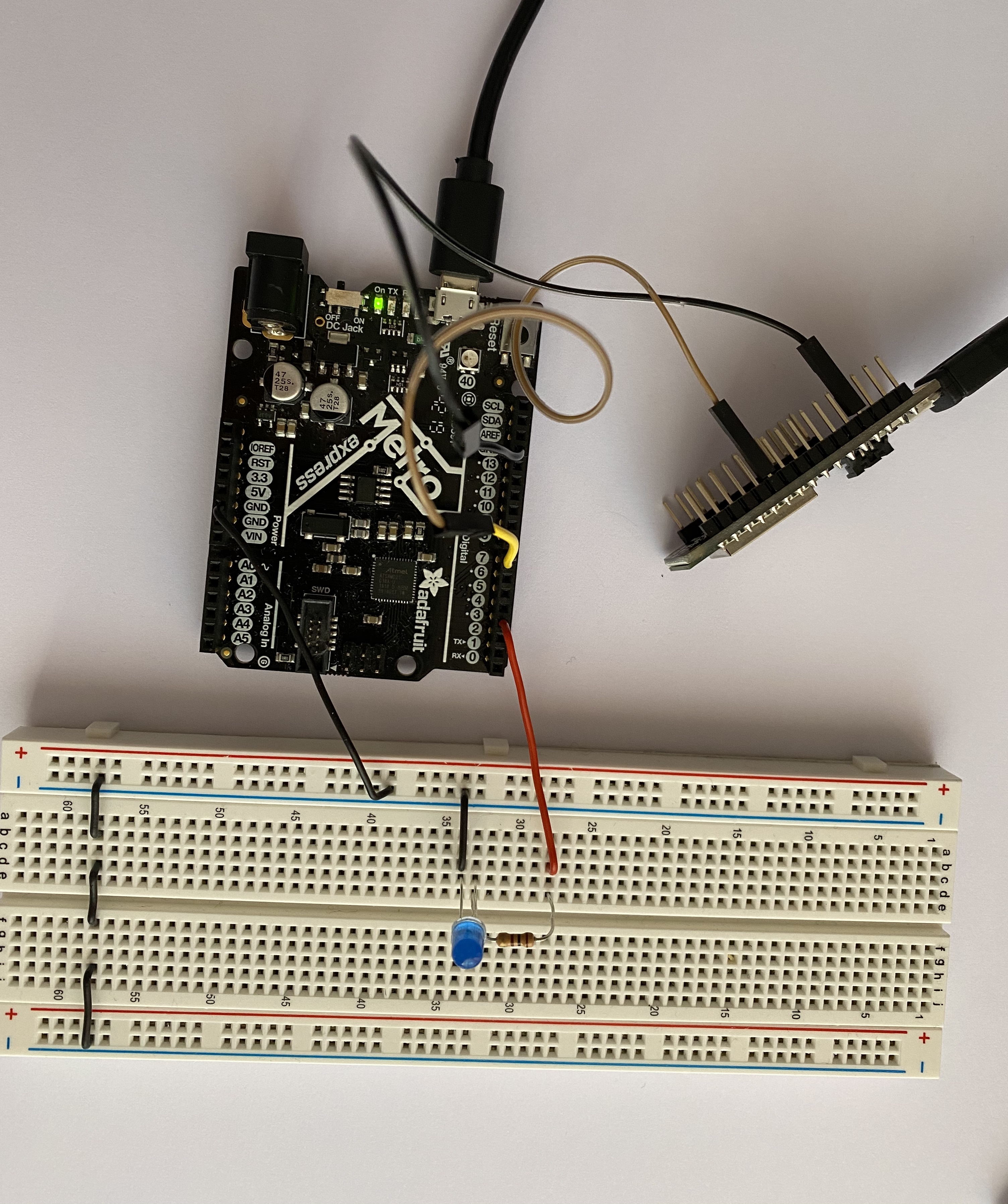
Firstly I made my ESP32 communicate with my Metro board through wire connections and wrote a simple program to see if the connection worked.
This is my circuit:
This is the program I uploaded to my ESP32 board:
            // program for the ESP32 board
void setup() {
  pinMode(5, OUTPUT); // set pin 5 as output to send signals to the Metro board
}

void loop() // Send "HIGH" signals for 5 seconds every 5 seconds
{
 if (millis%10000 > 5000){
  digitalWrite(5, HIGH);
  }
  else{
    digitalWrite (5, LOW);
    }

}
This is the program I uploaded to my Metro board:
            //PROGRAM FOR THE METRO BOARD

int input_pin;
void setup() {
  pinMode (7,INPUT); // set pin 7 as input to receive signals from the ESP32 board
  pinMode (3, OUTPUT); // set pin 3 as output to light the led


}

void loop() {
  input_pin = digitalRead(7);
  if (input_pin == HIGH) // if the ESP32 is sending an "HIGH" signal turn the LED on
  {
    digitalWrite(3, HIGH);
    }
  else {
    digitalWrite(3, LOW);} // if the ESP32 is sending a "LOW" signal turn the LED off
}
When I saw that the wire connection was working I tried to connect my ESP32 to the WiFi and try to light the LED in this way.
I uploaded the SimpleWiFiSever example to my ESP32. This program sends high signal to pin 5 when you press "click here to turn the LED on" and low signal when you press "click here to turn the LED off" so I uploaded the same program as before to my Metro, in fact this programs turns on the LED when the board receives "high" from pin 7 (the signal from the other board) and turns it off when pin 7 receives "low".
This is my circuit working:
I was now ready to control my little car through WiFi. I changed the ESP32 example program to make the web page show the right commands:
This is my code:
/*
 WiFi Web Server LED Blink

 A simple web server that lets you blink an LED via the web.
 This sketch will print the IP address of your WiFi Shield (once connected)
 to the Serial monitor. From there, you can open that address in a web browser
 to turn on and off the LED on pin 5.

 If the IP address of your shield is yourAddress:
 http://yourAddress/H turns the LED on
 http://yourAddress/L turns it off

 This example is written for a network using WPA encryption. For
 WEP or WPA, change the Wifi.begin() call accordingly.

 Circuit:
 * WiFi shield attached
 * LED attached to pin 5

 created for arduino 25 Nov 2012
 by Tom Igoe

ported for sparkfun esp32
31.01.2017 by Jan Hendrik Berlin

 */

#include < WiFi.h >

const char* ssid     = "your ssid";
const char* password = "your password";

WiFiServer server(80);

void setup()
{
    Serial.begin(115200);
    pinMode(5, OUTPUT);      // set the LED pin mode

    delay(10);

    // We start by connecting to a WiFi network

    Serial.println();
    Serial.println();
    Serial.print("Connecting to ");
    Serial.println(ssid);

    WiFi.begin(ssid, password);

    while (WiFi.status() != WL_CONNECTED) {
        delay(500);
        Serial.print(".");
    }

    Serial.println("");
    Serial.println("WiFi connected.");
    Serial.println("IP address: ");
    Serial.println(WiFi.localIP());

    server.begin();

}

int value = 0;

void loop(){
 WiFiClient client = server.available();   // listen for incoming clients

  if (client) {                             // if you get a client,
    Serial.println("New Client.");           // print a message out the serial port
    String currentLine = "";                // make a String to hold incoming data from the client
    while (client.connected()) {            // loop while the client's connected
      if (client.available()) {             // if there's bytes to read from the client,
        char c = client.read();             // read a byte, then
        Serial.write(c);                    // print it out the serial monitor
        if (c == '\n') {                    // if the byte is a newline character

          // if the current line is blank, you got two newline characters in a row.
          // that's the end of the client HTTP request, so send a response:
          if (currentLine.length() == 0) {
            // HTTP headers always start with a response code (e.g. HTTP/1.1 200 OK)
            // and a content-type so the client knows what's coming, then a blank line:
            client.println("HTTP/1.1 200 OK");
            client.println("Content-type:text/html");
            client.println();

            // the content of the HTTP response follows the header:
            client.print("Click < a href=\"/H\">here to make the car go forward on.< br>");
            client.print("Click < a href=\"/L\">here to make the car go backwards off.< br>");

            // The HTTP response ends with another blank line:
            client.println();
            // break out of the while loop:
            break;
          } else {    // if you got a newline, then clear currentLine:
            currentLine = "";
          }
        } else if (c != '\r') {  // if you got anything else but a carriage return character,
          currentLine += c;      // add it to the end of the currentLine
        }

        // Check to see if the client request was "GET /H" or "GET /L":
        if (currentLine.endsWith("GET /H")) {
          digitalWrite(5, HIGH);               // GET /H turns the LED on
        }
        if (currentLine.endsWith("GET /L")) {
          digitalWrite(5, LOW);                // GET /L turns the LED off
        }
      }
    }
    // close the connection:
    client.stop();
    Serial.println("Client Disconnected.");
  }
}
Then I wrote a program to make the stepper motors run in two different directions depending on the ESP32 board signals
This is my program:
      #include < Stepper.h>
int input_pin;
const int stepsPerRevolution = 200;

// initialize the stepper library
Stepper myStepper1(stepsPerRevolution, 8, 9, 10, 11);
Stepper myStepper2(stepsPerRevolution, 3, 4, 5, 6);


void setup() {
  // set the speed
  myStepper1.setSpeed(80);
   myStepper2.setSpeed(80);
  Serial.begin(9600);
  pinMode (7,INPUT); // set pin 7 as input to receive signals from the ESP32 board
  pinMode (3, OUTPUT); // set pin 3 as output to light the led
}

void loop() {

   input_pin = digitalRead(7);

 if (input_pin == HIGH ) {
  myStepper2.step(1);
  myStepper1.step(1);
 //move forward

  delay(1);
 }
 else {
  myStepper2.step(-1);
  myStepper1.step(-1);
 //move backwards
  }
}